
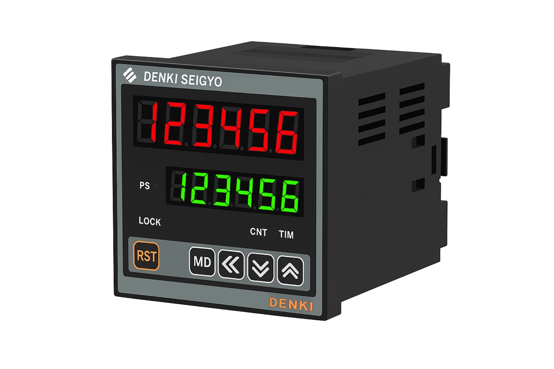

Electrical & Input Specifications
-
Power Supply / Rated Voltage: Typically 100 – 240 V AC 50/60 Hz (or optionally 24 V DC variant)
-
Operating Voltage Range: approx. ±10 % of rated supply
-
Sensor / Input Types Supported:
-
Pulse input (e.g., contact closure, transistor or opto‑isolated input)
-
Start/Stop/Gate control signals (for timer function)
-
Reset/Preset inputs (to set initial value or target)
-
-
Counting Speed / Frequency: Capable of processing high‑speed pulses (e.g., up to several kHz) and synchronizing counting/timing with minimal interruption (modern modules may pause count for only ~120 ns during read‑out).
-
Preset / Setpoint Range: Multi‑digit display (e.g., 4‑6 digits) allowing counts from 0 up to 999999 or more depending on model.
-
Display & Interface: Dual or single display of process value (count/time) and setpoint; front panel keys for control, reset and configuration.
Mechanical & Mounting Specifications
-
Panel Cut‑out / Case: Standard panel‑mounting module (sizes such as 48×48 mm, 72×72 mm, 96×96 mm common in industrial controllers)
-
Depth & Weight: Depth behind panel typically ~100‑120 mm; weight moderate for panel unit (couple of hundred grams to ~1 kg depending on variant)
-
Terminal Connections: Heavy duty screw terminals or plug‑in connectors for power, signal inputs, outputs; separate terminals for count inputs, control inputs, reset/preset, etc.
-
Ambient Temperature Range: -10 °C to +50 °C (typical) — non‑condensing environment recommended
-
Storage Temperature: usually down to –20 °C and up to +70 °C
-
Housing / Front Protection: IP rating (front bezel) often IP65 when correctly sealed, to protect from dust and splash (verify model)
-
Insulation/Withstand Voltage: e.g., 1,000 V AC between power terminals and earth (typical industrial spec)
Functional Characteristics
-
Counting Modes: Up‑counter, down‑counter, preset counter (stop or alarm at preset).
-
Timing Modes: Elapsed time measurement, countdown timer, cyclical timing, gate/time gating.
-
Preset Functionality: On reaching a preset count/time, output actuates (relay or SSR) or an alarm is triggered.
-
Control Inputs: Start, Stop, Reset, Gate functions configurable via front panel or wiring.
-
Output(s):
-
Relay output (SPDT or DPDT) rated for AC or DC loads (e.g., 250 V AC, 2–5 A)
-
Solid‑state/SSR driver output (12 V DC drive, ~20‑50 mA) in some variants
-
Optional analog retransmission output (0‑10 V or 4‑20 mA) representing count/time value (if model supports)
-
-
Accuracy & Stability: High‑speed counting with minimal dead‑time during data read‑out (e.g., pause ~120 ns) ensures negligible error even when read frequently.
-
Memory: Non‑volatile memory stores settings and count/time values upon power‑loss (in many models).
-
Front Panel Indicators: LED or digital display for power, output state, alarm status, gate signal etc.
Protection & Environment
-
Input protection: Noise filtering and debouncing on high‐speed pulses; minimum pulse width filter (e.g., enable “MIN10U” mode for minimum 10 µs pulses).
-
Over‑voltage/Surge protection: Internal protection or recommended external surge arrestors in high noise industrial environments
-
Hygiene / Vibration / Shock Resistance: Suitable for industrial vibration/shock environments when mounted properly; check model for values
-
Relative Humidity: Typically up to ~90% RH non‑condensing; ensure ambient is free of corrosive gases.
-
Altitude: Usable typically up to ~2,000 m without derating; check manufacturer spec for higher altitudes.
Installation & Maintenance Guidelines
-
Mount the unit in a well‑ventilated panel space, avoid direct heat sources and ensure clearance for wiring.
-
Use shielded cables for signal/pulse inputs if in a noisy environment with heavy switching motors nearby.
-
Ensure power supply is stable and within rated range; use clean DC or AC supply as required.
-
Configure inputs (start/stop/reset/gate) via front panel or via wiring as per manual; verify pulse width thresholds if dealing with high‐speed pulses.
-
Periodically check display readability, wiring terminal tightness, output relay state/contacts, and verify no buildup of dust or debris in panel ventilation.
-
For models with analog retransmission or communication, verify calibration as per manual at installation and at periodic intervals.
Typical Applications
-
Batch counters and process timers in automation lines (bottling, packaging)
-
Event counters in manufacturing (cycles, pieces, parts)
-
Elapsed‐time monitoring of machinery or equipment (maintenance scheduling)
-
Gate/timer logic control in machine operation sequences (e.g., hold period then release)
-
High‐speed pulse counting (e.g., from encoders, proximity switches) in process monitoring.