
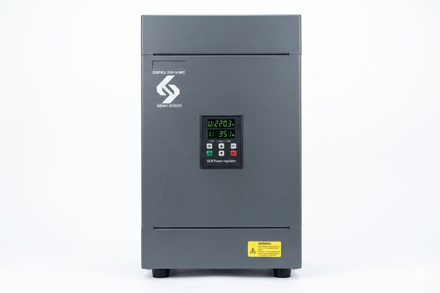
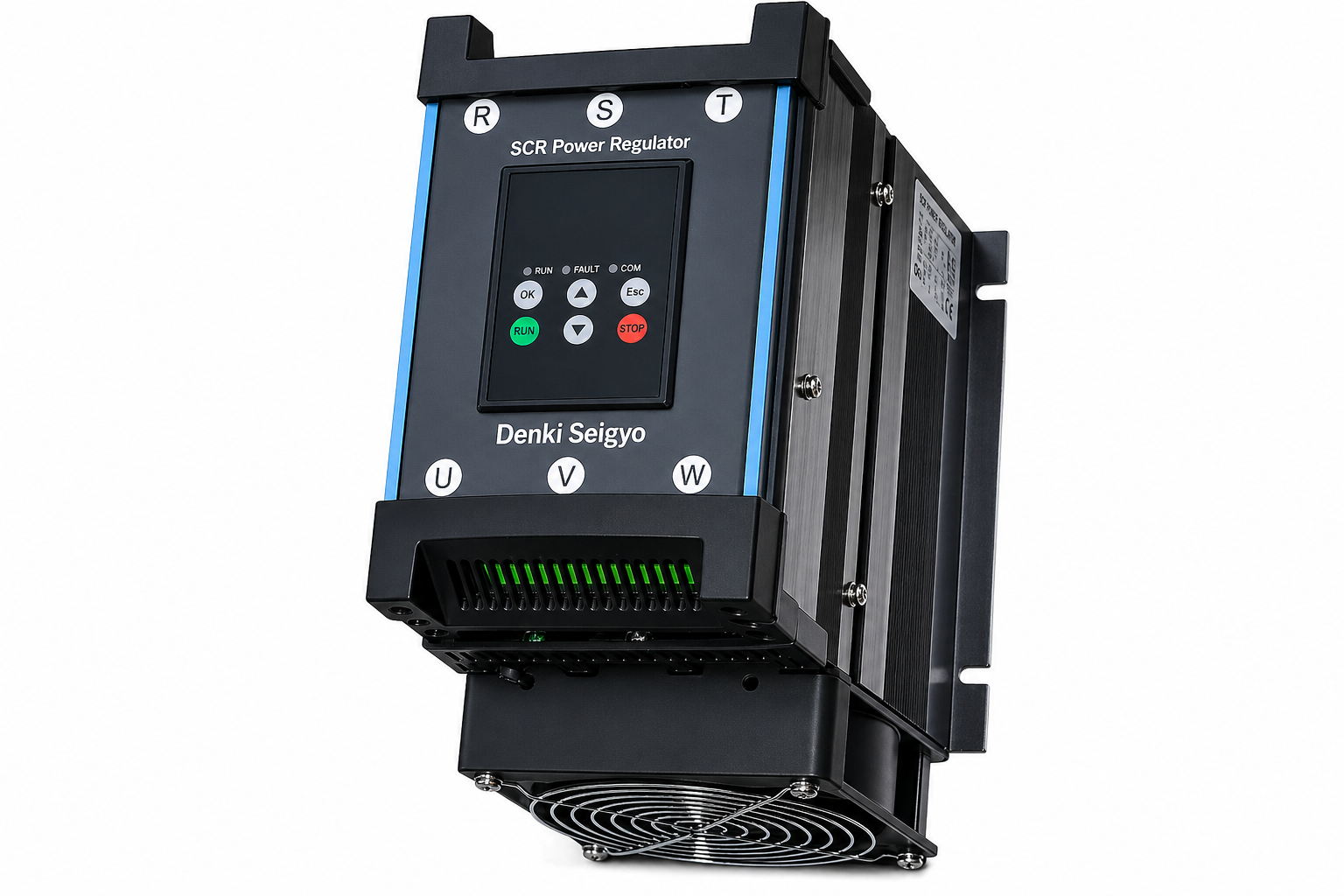
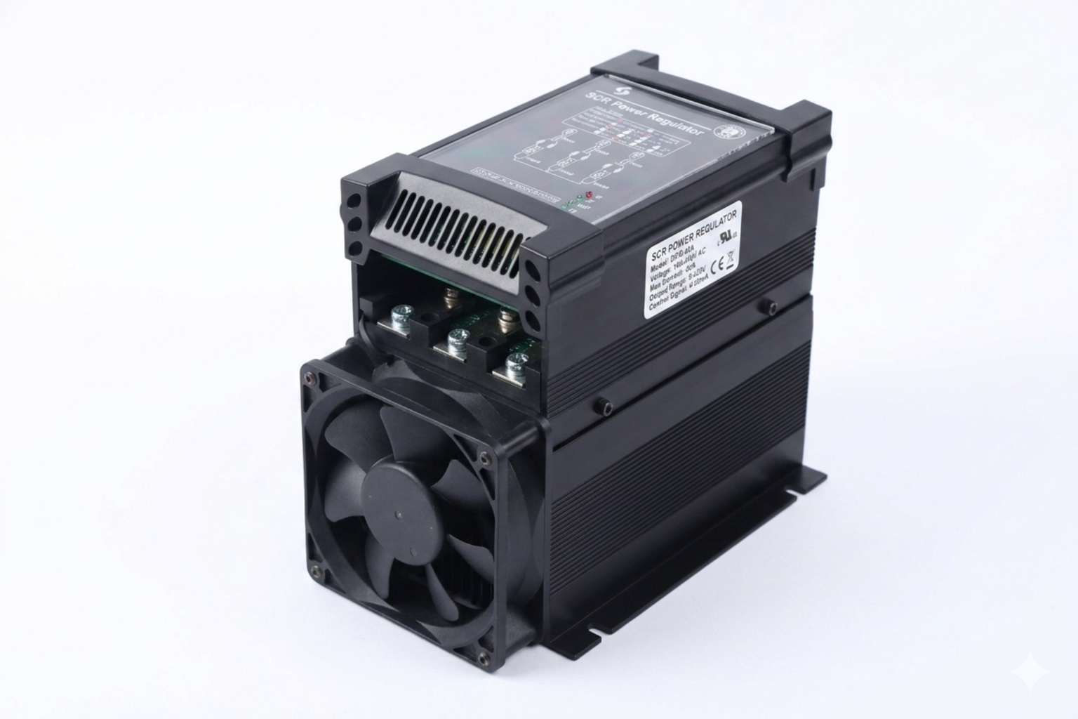
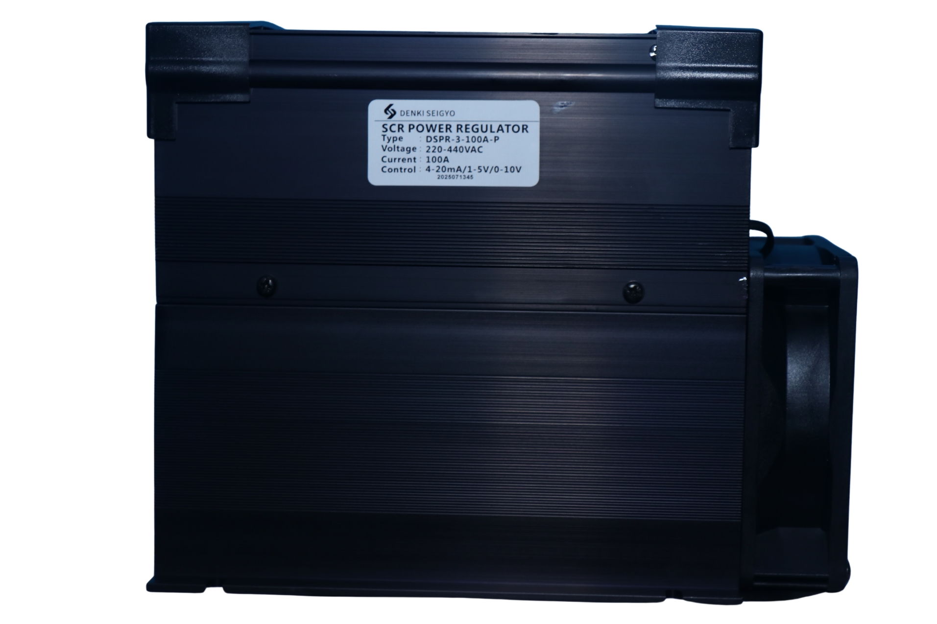
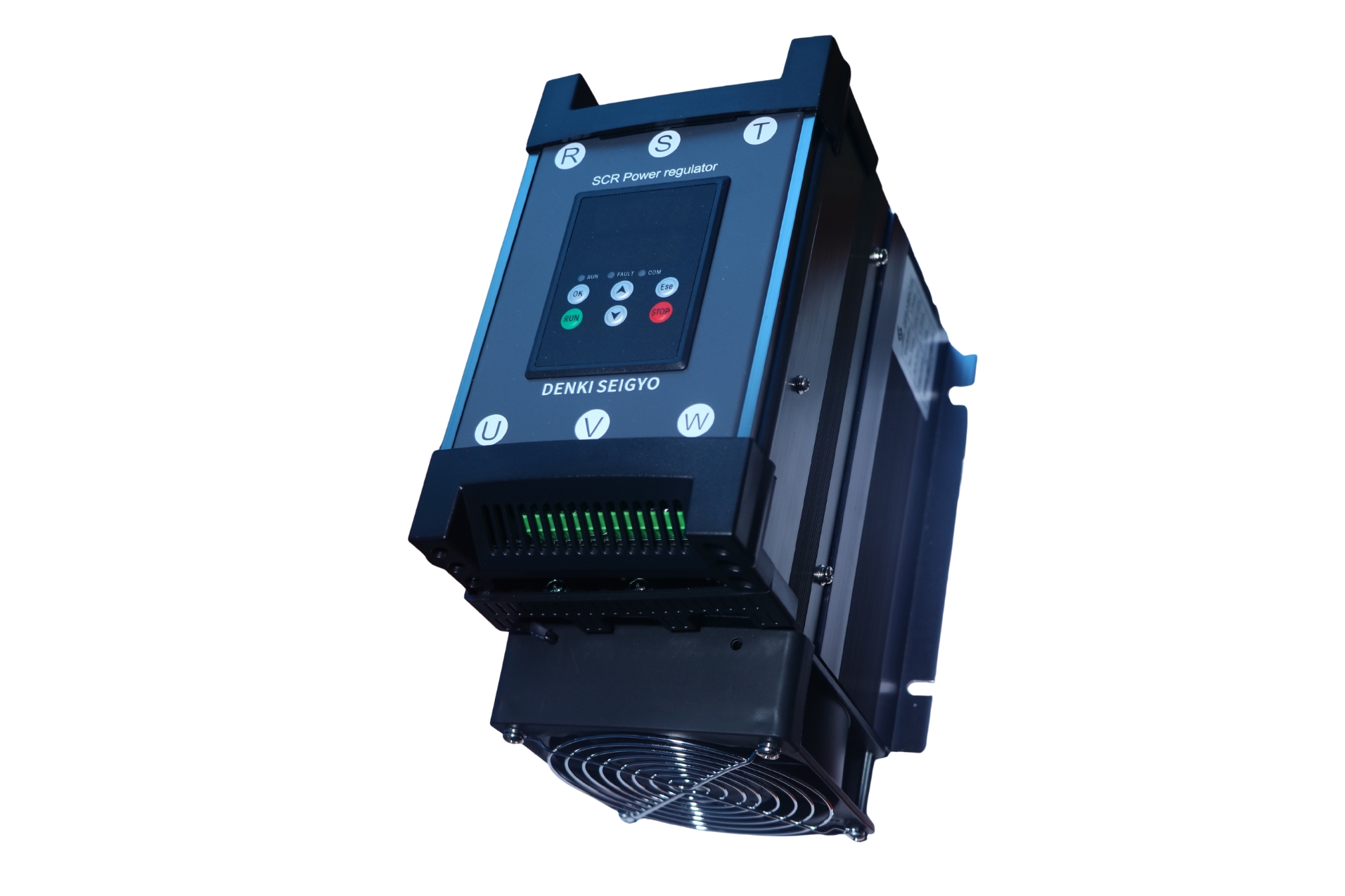
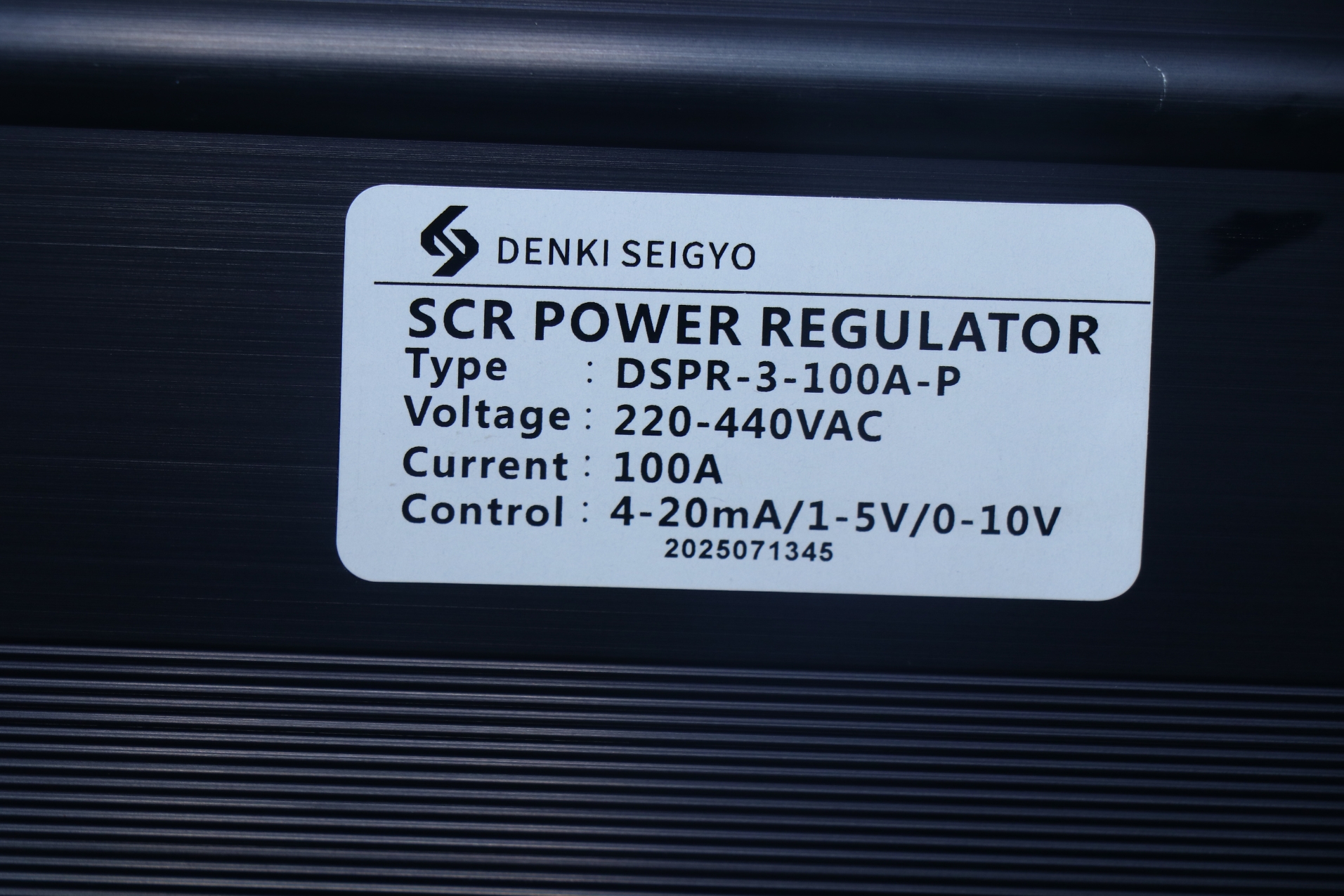
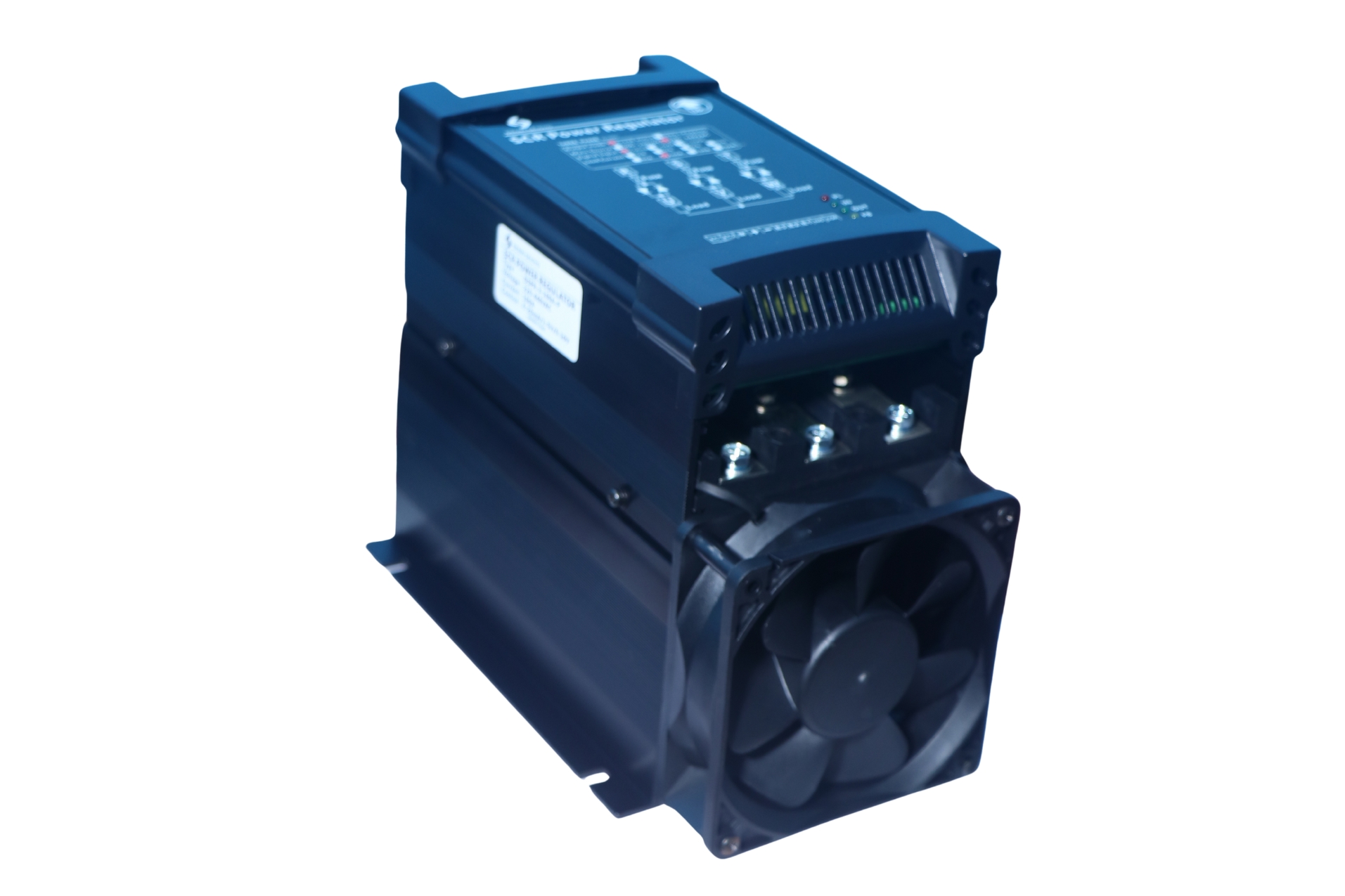



Electrical Specifications
-
Supply voltage (three‑phase): Typically 380‑480 V AC (or variant 200‑240 V/415‑480 V) at 50/60 Hz.
-
Current rating: Many models are rated from tens of amperes up to several hundred amperes. For example, typical three‑phase thyristor regulators may range from 25 A to 1000 A according to the manufacturer’s product class.
-
Control input: Analogue (e.g., 0‑10 V, 4‑20 mA) or digital input; galvanically isolated from power circuit.
-
Control mode: Phase‑angle control (adjusting conduction angle each half‑cycle) or burst‑fire control (switching full cycles) or combination, to accommodate different load types (resistive vs inductive).
-
Load type compatibility: Supports resistive loads (heaters), inductive loads (motors, coils) and mixed loads when properly selected.
-
Minimum load requirement / leakage current: Some modules require minimum current to guarantee stable triggering; leakage when off should also be specified.
-
On‑state voltage drop / dissipation: The thyristor module dissipates some heat during conduction; ensure heatsink and ambient conditions are accounted for.
-
Power regulation range: 0‑100% of load (depending on control signal and conduction angle).
-
Response time: Very rapid compared to mechanical switches — in the order of milliseconds from control signal change to output adjustment.
Selection Chart
| Model | Phase | Rated Current | Control Mode | Communication | Typical Input Signal | Output Voltage Range | Remarks |
|---|---|---|---|---|---|---|---|
| DSPR-3-60A-P | 3φ | 60A | Phase control | None | 4–20 mA / 0–10 V (opt.) | 230/400/440 VAC | Standard model |
| DSPR-3-100A-P-WC | 3φ | 100A | Phase control | RS-485 (WC) | 4–20 mA / 0–10 V + Modbus | 230/400/440 VAC | With communication |
| DSPR-3-130A-P | 3φ | 130A | Phase control | None | 4–20 mA / 0–10 V (opt.) | 230/400/440 VAC | Standard model |
| DSPR-3-160A-P-WC | 3φ | 160A | Phase control | RS-485 (WC) | 4–20 mA / 0–10 V + Modbus | 230/400/440 VAC | With communication |
| DSPR-3-200A-P | 3φ | 200A | Phase control | None | 4–20 mA / 0–10 V (opt.) | 230/400/440 VAC | High current model |
| DSPR-3-1000A-P-WC | 3φ | 1000A | Phase control | RS-485 (WC) | 4–20 mA / 0–10 V + Modbus | 230/400/440 VAC | High current + comm |
Model Code Breakdown – DSPR-3-100A-P-WC
| Code Part | Example Value | Meaning |
|---|---|---|
| Series | DSPR | Denki Seigyo Power Regulator (Thyristor) |
| Phase Type | 3 | 3-Phase |
| Current Rating | 100A | Rated current 100 Ampere |
| Load Type | A | AC load / standard type |
| Control Mode | P | Phase control |
| Communication | WC | With communication (RS-485 / Modbus) |
Mechanical & Mounting
-
Mounting type: Unit is designed for panel or chassis installation; heavy‑duty terminals for each phase, separate control terminal block.
-
Cooling requirement: External heatsink or integral heatsink with forced ventilation may be required when operating near the rated current, or in high ambient temperature.
-
Dimensions & weight: Varies by current rating; larger current models are physically larger and heavier.
-
Terminals: Load side screws/busbars capable of rated current, control input terminals for analogue/digital wiring.
-
Ambient temperature rating: For example, typical industrial modules might operate from −10 °C to +50 °C (derating above +40 °C).
-
Mounting clearance: Adequate airflow and clearance around the unit to dissipate heat; usually top/bottom or side clearance specified.
Environmental & Protection Features
-
Operating temperature range: As above; storage temperature typically wider (e.g., −20 °C to +70 °C).
-
Humidity: Non‑condensing environment up to, e.g., 90% RH (verify for the unit).
-
Over‑temperature protection: Built‑in thermal cut‑out or sensor to shut down or derate in case of heatsink overheating.
-
Over‑current / short‑circuit protection: Unit may have current‑limit or trip functions; upstream protection (semiconductor fuses or circuit breakers) recommended.
-
Galvanic isolation: Control circuit isolated from mains to meet safety standards.
-
Ingress Protection / Safety: Enclosure rating (IP20 or higher, if applicable); compliance with IEC/EN standards for industrial power modules.
-
EMI / harmonic considerations: Because phase‑angle switching produces harmonics and transients, it’s recommended to use filters, snubber networks and proper grounding practices.
-
Altitude, vibration, shock: Standard industrial ratings apply; check the datasheet for details on vibration and shock tolerance.
Functional Characteristics
-
Switching mode:
-
Phase‑angle mode: thyristor triggers at adjustable angle in each half‑cycle; provides fine control of output voltage.
-
Burst‑fire mode: full cycles are switched on/off; useful for inductive/heavy loads or high inertia systems.
-
-
Control signal mapping: Linear relationship between input (0‑10 V or 4‑20 mA) and output power/voltage (0‑100%).
-
Linearity and repeatability: Good precision of output relative to control signal, enabling stable process control.
-
Minimum load / leakage: Some units require a minimum load current for stable conduction; also may have a small leakage current when off—important for sensitive loads.
-
Heat dissipation and derating: As current increases or ambient temperature rises, unit may need derating (reduce current) to maintain safe junction temperature.
-
Maintenance & indication: Some units include LED indicators or status outputs (fault, phase loss, over‑temperature) for alarm and monitoring functionality.
-
Integration: Suitable for control panels—may interface with PLCs or automation systems. Provide appropriate wiring, control wiring separation, and grounding.
Certifications & Compliance
-
CE marking (for European‑compatible versions).
-
RoHS compliance (lead‑free components).
-
Designed per industrial switching device standards (e.g., IEC 60947, IEC 60068 for environmental).
-
Safety agency approvals may apply depending on region / variant.
-
Datasheet must be consulted for local product variant and compliance to Indian standards (e.g., IS/IEC, BIS) if used in India.
Installation & Maintenance Guidelines
-
Mount the regulator on a flat metal surface or dedicated heatsink; ensure ventilation and clearance as per datasheet.
-
Use cables and busbars rated for the current plus margin; tighten terminals to specified torque to avoid hot spots.
-
Provide semiconductor‑grade fusing or circuit breaker upstream.
-
Separate high‑current wiring and control wiring to avoid interference; shield control wiring if required.
-
Inspect periodically: ensure heatsink remains free of dust, verify that terminal temperature is within acceptable limits (no hot spots).
-
When operating near maximum rating or in elevated temperature, consider forced cooling or derated operation.
-
Replace or service the unit if any indicators show fault, or if terminal connections show signs of overheating (discolouration, oxidation).
Typical Applications
-
Large three‑phase heater banks in industrial ovens, kilns, drying lines or thermal processes.
-
Three‑phase motor power regulation for conveyors, mixers, pumps (when speed/power modulation required).
-
Transformer loads or induction heating systems requiring smooth power control.
-
Automation‑controlled manufacturing equipment where precise three‑phase power modulation is critical.